
Abstract
Humanoid robots performing navigation and obstacle avoidance typically rely on perception that is either external and prepared ahead of time, or fixed to the robot's body, limiting them to a single region of interest at a time. In this work, we equip a Unitree G1 humanoid with a 2-DOF pan-tilt head that decouples camera orientation from body orientation, and evaluate it on two tasks that require continuous, actuated perception of a moving target.
In the first task, the robot must track a moving ball with the head while an MPC and a CBF-QP safety filter govern body navigation around obstacles, using a color-based (HSV) and neural (YOLOv11n, YOLOE-26) detector pipeline evaluated for both detection and onboard inference latency. In the second task, we build on a prior kick-imitation policy and design a policy that decides when and where to kick, improving the direction of the baseline kick. Together with an interception planner, this achieves a continuous wall-rally kick. Using only onboard perception, the same control loop sustains a rally of 8 kicks, limited mainly by motion-induced sensing noise.
These results show that decoupling perception from body orientation through an actuated head lets a humanoid keep a target in view and act on it, across both a safety-filtered navigation task and a precision manipulation task, without relying on external infrastructure or a body-fixed viewpoint.
Ongoing work includes improving the kicking policy with adversarial motion priors, adding onboard odometry to remove the remaining ground-truth dependency, and validating both tasks on the physical pan-tilt head.
Keywords: humanoid robots, actuated perception, pan-tilt, safety filters, control barrier functions, model predictive control, imitation learning.
Introduction
Motivation and Background
Modern humanoid locomotion increasingly relies on exteroceptive perception for tasks such as foothold planning[1,2], navigation[3,4], and obstacle avoidance[5]. Each of these tasks demands a different kind of information from the environment, and each solves that demand with a different sensing strategy.
In foothold planning, the goal is for the robot to walk over sparse footholds at varying distances, such as stairs up, stairs down, flat stones, and height-varying stones, or footholds with lateral constraints. One approach trains a locomotion policy with reinforcement learning guided by model-based references, and at deployment, the robot's pose is tracked by an external motion capture system, with elevation maps built in advance by ray-casting onto a mesh that matches the physical testbed[1]. A related approach follows a similar model-guided reinforcement learning strategy, and at deployment, perception is provided by an onboard depth camera mounted on the chest, pointed forward and down[2].
In navigation, the robot must move through terrain such as stairs, or through spaces shared with humans and obstacles. One method trains a layered controller in two stages: a proprioceptive stabilizer first, then a navigation layer conditioned on a local heightmap; at deployment, this heightmap is built from two onboard cameras, one on the back of the hips and one on the chest, both pointing down[3]. Another applies a dual-layer safety filter, combining an MPC layer and a CBF layer, built around a social-semantic guidance field constructed from a semantic occupancy grid, which on a quadruped is built using an active sensing gimbal, but on the G1 humanoid is built from only a fixed, forward-facing camera and no gimbal[4].
For obstacle avoidance, a predictive safety filter using an MPC-CBF formulation generates its safety constraint by solving Poisson's equation over an occupancy map; at deployment, this occupancy map is built from an overhead camera external to the robot, infrastructure fixed in the environment rather than carried by the robot[5].
Problem Statement and Proposed Approach
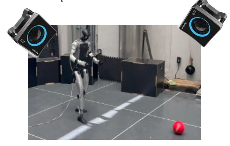
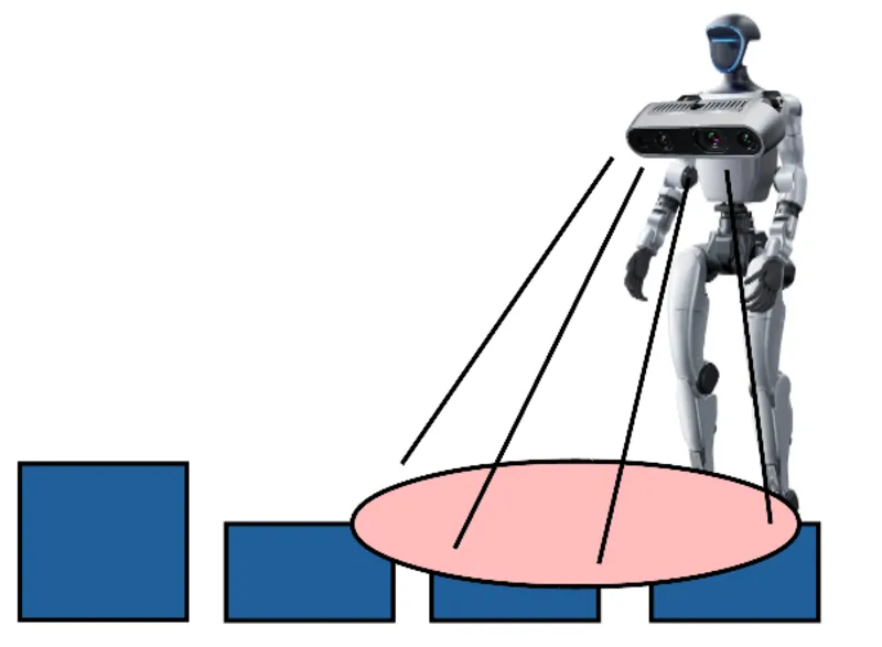
Grouped by sensing strategy, these approaches fall into three cases: perception external to the robot, prepared ahead of time; perception onboard but with a fixed viewpoint; and perception onboard and actuated, though only on one of the two platforms it was tested on. Each case carries a distinct limitation. External perception depends on infrastructure fixed in the environment beforehand, so it cannot be deployed in real time in an uncontrolled setting. A fixed onboard viewpoint limits the robot's ability to achieve highly dynamic, long-horizon maneuvers that require planning several steps ahead.
In each case, the robot does obtain the environmental information its task requires, but only for one region of interest at a time, and only under conditions, prepared infrastructure or a body-fixed viewpoint, that do not hold once the robot is deployed in real time, in an uncontrolled environment.
Main contribution
As a solution to this, we introduce an actuated sensing module that decouples the camera's orientation from the body, allowing the robot to acquire observations independently of its body orientation. Specifically, a pan-tilt mechanism mounted on the head expands the robot's long-horizon perception by reorienting the camera toward the region of interest without requiring the body to turn. This addresses the limitation identified above by treating perception itself as an actuated degree of freedom, rather than adding a new sensor with a different fixed viewpoint.
Approach
To validate this addition, the evaluation environment must reproduce a setting where the camera has to be onboard and must continuously follow a changing region of interest: a target that moves outside the body's field of view, requiring continuous re-observation.
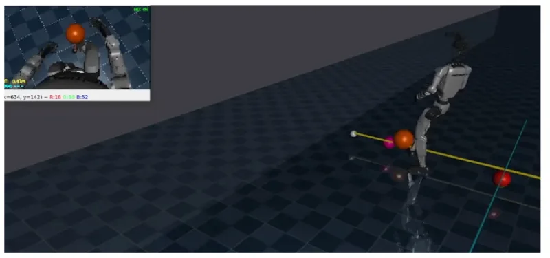
We build two scenarios for validation. In the first, a tracking task, the robot has three simultaneous tasks: the pan-tilt mechanism continuously tracks a ball, the body reduces the distance between the robot and the ball, and the body avoids obstacles. In the second, a kicking task, the robot has two simultaneous tasks: the pan-tilt tracks the ball, and the body decides when and where to kick the ball against a wall so as to maximize the number of kicks.
Chapter 1: Redesign and Fabrication of the Humanoid's Head
Mechanical Design
The mechanical design of the pan-tilt module is based on the geometry, mass, and kinematics requirements: the new head must not exceed the dimensions of the Unitree G1's original head, its total mass must be less than 3 kg, and it must have two independent degrees of freedom, pan from -100° to 100° and tilt from -60° to 120°.
The pan axis rotates about the neck's vertical axis, while the tilt axis, mounted on the pan link, orients the camera in elevation; the two axes are independent of each other, so the final camera orientation is the composition of both rotations.
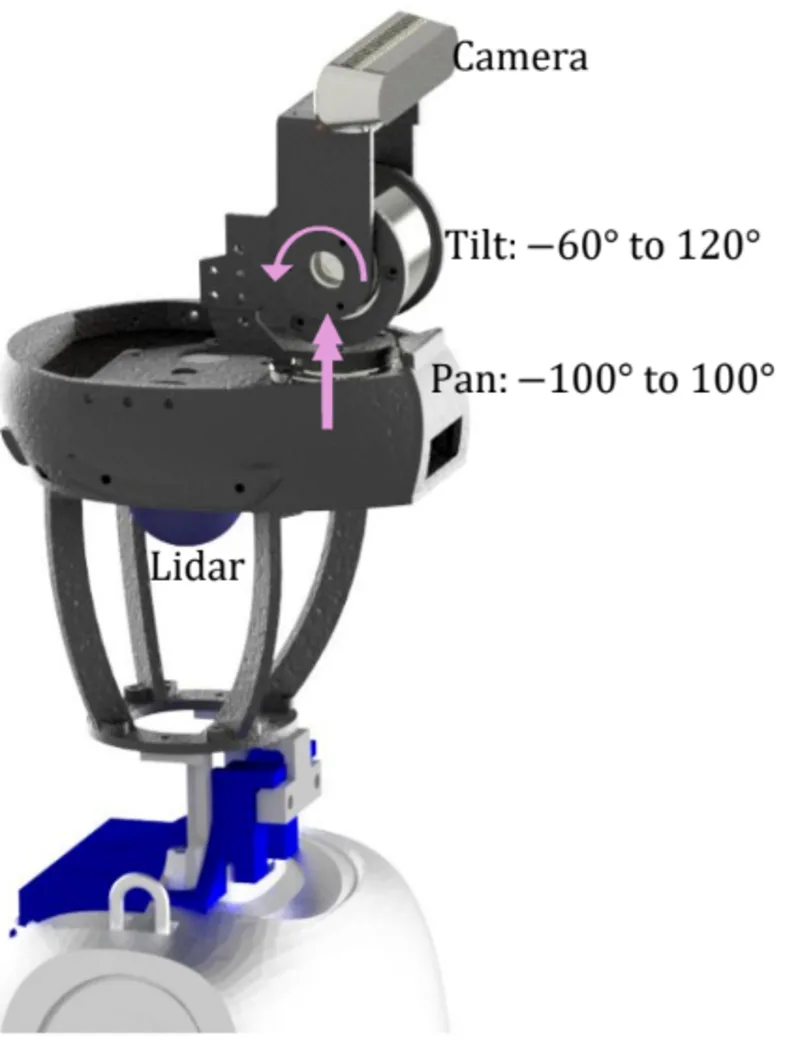
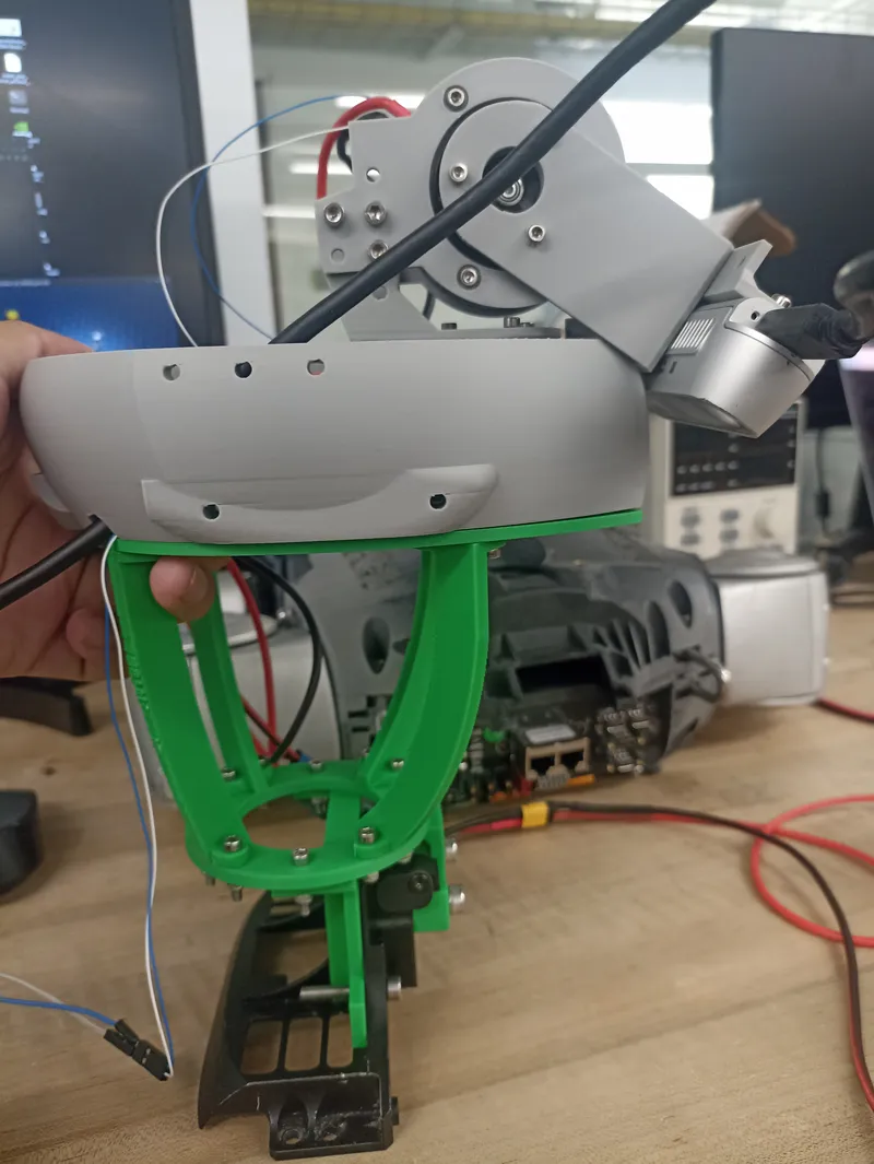
The pan-tilt module mounts directly onto the G1's factory neck, so the original head can be swapped for the new one using the same mounting points, without machining the body or altering its external geometry. The interface uses 3D-printed couplers oriented at 45° rather than the robot's original axes, reducing the occlusion this structure introduces on the LiDAR's field of view.
The camera's 72 g weight was not the driving load case; control quality was, since the structure and actuators need enough margin to reject gait-induced vibration without losing tracking precision. This is why we selected the AK40-10 from CubeMars[6]: its 4.1 N·m peak torque leaves wide margin for disturbance rejection, at just 185 g per unit.
Electronic Design
The module runs on the G1's own 24 V battery output and communicates over CAN through a Jhoinrch RH02 Plus adapter[7]. Position sensing and environment perception reuse hardware already on the robot: the AK40-10 actuators'[6] integrated encoders, plus the G1's own RealSense D435i camera and Livox Mid-360 LiDAR[8], relocated to the new head instead of added new.
Chapter 2: Active Perception in Safe Avoidance Tracking (Task 1)
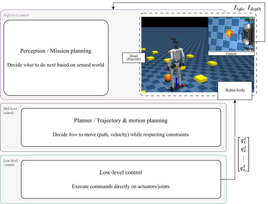
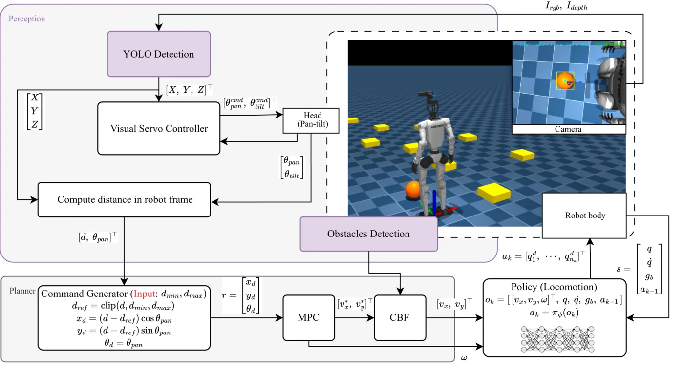
This chapter details the design of the simulation environment and the controllers for the tracking-with-obstacle-avoidance task, following a layered control paradigm in which the high level handles perception, the mid level handles navigation planning, and the low level is the locomotion policy that directly commands the robot's motors.
Simulation Environment
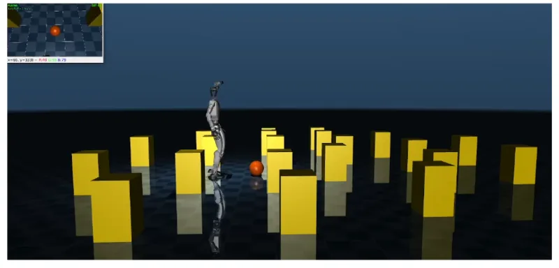
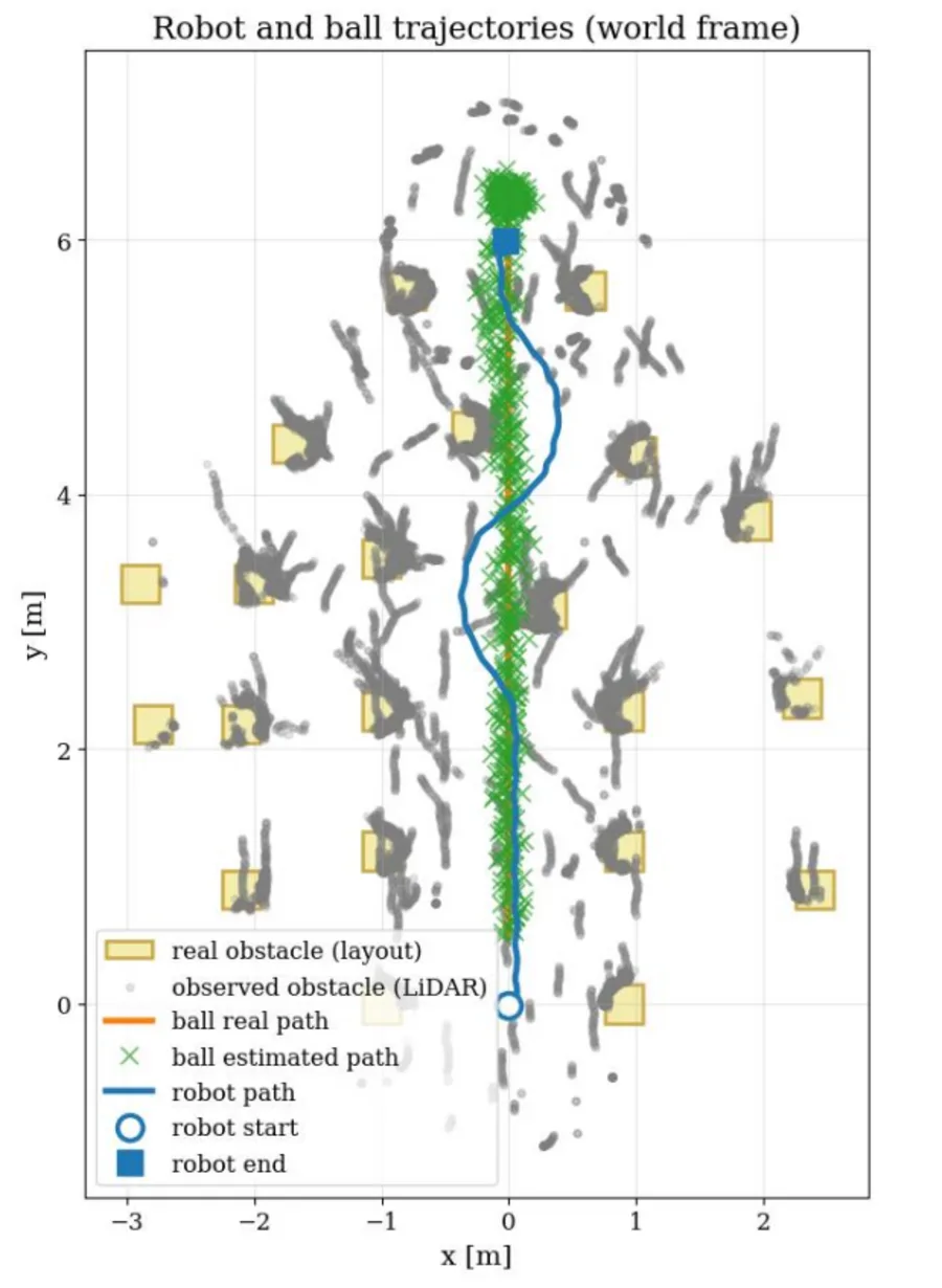
The simulated Unitree G1, modified with the pan-tilt head and camera, operates in an environment with obstacles (0.3 m × 0.3 m base, 0.5 m height) and a circular target (radius 0.11 m) that moves along the ground, simulating a region of interest the robot must continuously follow, such as another agent in a collaborative task or a reconnaissance drone guiding the robot through rubble. The task's complexity comes from the robot having three simultaneous jobs: following the object with the pan-tilt, reducing the distance to it, and avoiding obstacles, using only the head-mounted camera and LiDAR, with off-board perception ruled out.
High Level: Perception
Since two sensors are used, each has an independent task: the LiDAR detects obstacles, and the camera detects and tracks the target. For the camera's task, the first step converts image information into pan-tilt actuation commands and, in addition, commands for the mid-level control. The LiDAR's goal is to provide obstacle position information to the mid-level control, reproducing the real layered blind-zone geometry of the Livox Mid-360 sensor[8].
Detector: HSV and YOLO
For the first stage, a color-based HSV detector was used: detection is efficient given the idealized MuJoCo environment's lighting and the target's characteristic orange color, and running a neural network such as YOLO during parallelized training was prohibitive for the laptop used (GTX 1650 Ti, 4 GB). To validate feasibility and the influence of latency on the controllers, the detection was also tested on a Jetson AGX Thor (70 W mode) using YOLOE-26[9], which correctly detected the ball via the prompt “orange ball,” while YOLOv11n[10] could not detect it as the ball class, but could as the “orange” class.
| Detector | Latency |
|---|---|
| YOLOv11n | 20-25 ms |
| YOLOE-26 | 30-35 ms |
Both latencies are comparable to, or exceed, the 20 ms period of the 50 Hz control loop by themselves, without counting additional transport delay or inference queuing, so a single detection can already lag the control loop by one cycle or more. The detector's goal is to provide the object's position \(( X, Y, Z )\), using the factory Intel RealSense D435i depth camera relocated to the pan-tilt module.
From Pixel Detection to 3D Position
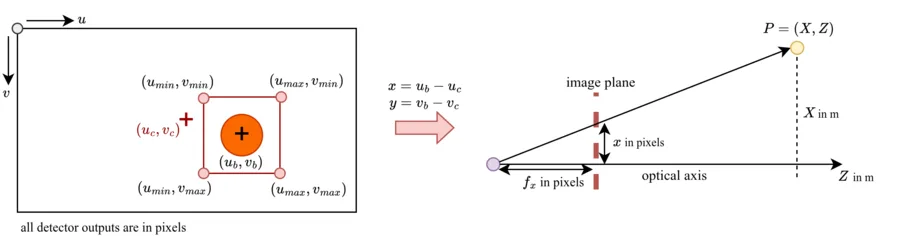
The detector outputs the ball detection as a bounding box in pixels. From this, the midpoint of the box is computed, and then its displacement with respect to the image center via a direct subtraction,
\[ x = u_b - u_c, \qquad y = v_b - v_c, \]
and then, using the camera's intrinsic focal lengths \(f_x, f_y\), the ball's position in meters is computed via similar triangles,
\[ X = \frac{x\,Z}{f_x}, \qquad Y = \frac{y\,Z}{f_y}, \]
where \(Z\) is obtained directly from the depth sensor, without needing to estimate it geometrically.
Visual Servo Control
This controller keeps the ball at the center of the image. Rather than using a raw pixel error, the error is defined as the angle subtended by the ball's position with respect to the camera's optical axis,
\[ e_x = \tan(\theta_{pan}) = \frac{X}{Z}, \qquad e_y = \tan(\theta_{tilt}) = \frac{Y}{Z}, \]
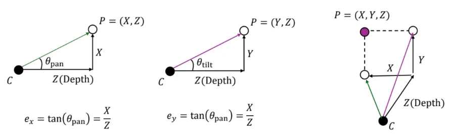
The controller's output is the pan-tilt update, a step proportional to the error,
\[ \begin{aligned} \theta_{pan}^{k+1} &= \operatorname{clamp}\!\left(\theta_{pan}^{k} + k_p\, e_x\, \Delta t,\ \theta_{min},\ \theta_{max}\right) \\ \theta_{tilt}^{k+1} &= \operatorname{clamp}\!\left(\theta_{tilt}^{k} + k_p\, e_y\, \Delta t,\ \theta_{min},\ \theta_{max}\right) \end{aligned} \]
where \(k_p\) is the proportional gain and \(\Delta t\) the control period; \(\operatorname{clamp}\) saturates the output to the pan-tilt's mechanical limits.
Forward Kinematics: From Pelvis to Camera
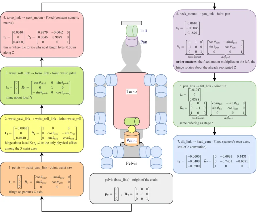
Since the target's position was obtained with respect to the camera's frame, and all controllers are developed with respect to the robot's pelvis, each of the 7 stages of the pelvis-camera chain is written as a homogeneous transformation matrix relating frame \(i\) to its parent \(i-1\),
\[ T^{i}_{i-1} = \begin{bmatrix} \bar R_i & t_i \\ 0^\top & 1 \end{bmatrix}. \]
Chaining all 7, the camera's pose with respect to the pelvis is
\[ T^{cam}_{pelvis} = T^{waist\_yaw}_{pelvis}\, T^{waist\_roll}_{waist\_yaw}\, T^{torso}_{waist\_roll}\, T^{neck}_{torso}\, T^{pan}_{neck}\, T^{tilt}_{pan}\, T^{cam}_{tilt} = \begin{bmatrix} R^{cam}_{pelvis} & p^{cam}_{pelvis} \\ 0^\top & 1 \end{bmatrix}. \]
With \(R^{cam}_{pelvis}, p^{cam}_{pelvis}\) known, the target's position as measured by the camera is expressed with respect to the pelvis via the same transformation,
\[ p^{target}_{pelvis} = R^{cam}_{pelvis}\, p^{target}_{cam} + p^{cam}_{pelvis} = (b_x,\, b_y,\, b_z)^\top. \]
From this, the distance \(d\) and heading \(\theta_{pan}\) used by the mid-level Command Generator follow directly:
\[ d = \sqrt{b_x^2+b_y^2}, \qquad \theta_{pan} = \operatorname{atan2}(b_y, b_x). \]
Obstacle Detection and Memory
Each obstacle is obtained directly from LiDAR clustering: each scan yields, for each obstacle, its center and radius in the body frame, without estimating velocity. Association between successive scans is done by nearest neighbor (0.5 m match radius), and an obstacle is kept for up to 1 s without being seen; in the meantime, it stays at its last detected position and is not predicted forward. The list is sorted by proximity and truncated to the 30 closest obstacles before being passed to the mid level.
Mid Level: Planning
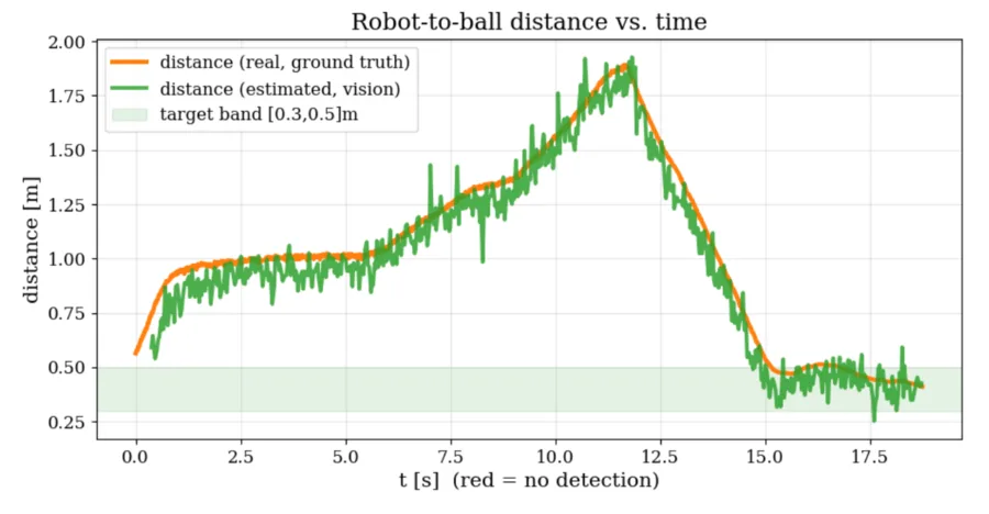
The Command Generator produces the navigation reference from the distance and heading estimated by perception, keeping the robot within a desired distance band \([d_{min}, d_{max}]\), with \(d_{min}=0.30\) m and \(d_{max}=0.50\) m:
\[ d_{ref} = \operatorname{clip}(d, d_{min}, d_{max}). \]
The desired distance is then decoupled into \(x_d, y_d\) using the pan angle read by the encoder:
\[ x_d = (d - d_{ref}) \cos\theta_{pan}, \qquad y_d = (d - d_{ref}) \sin\theta_{pan}, \qquad \theta_d = \theta_{pan}. \]
The robot's desired heading is set to the pan angle: since the pan has a limited range, the body is also expected to contribute to the tracking, so the pan-tilt reacts fast (low inertia) while the robot's body, with greater inertia, takes longer. Rather than embedding the safety constraint directly into the MPC horizon as a single QCQP[5], the controller solves, at each step, two separate and sequential QPs: first a tracking MPC with no safety constraint, then a CBF-QP filter that corrects that output to make it safe.
Tracking MPC
Since the low-level locomotion policy requires \(v_x, v_y, \omega\) as inputs, the robot is reduced to a single-integrator model, with state \(\xi = (x, y, \theta)\) and dynamics
\[ \xi_{k+1} = \xi_k + dt\, u_k, \qquad u_k = (\dot x_k, \dot y_k, \omega_k). \]
At each step the robot is taken as the origin of the frame, since its global position is not of interest, only its relative position to the target. The cost considers tracking error against the reference from the Command Generator plus control effort, subject to the robot's motion limits:
\[ \begin{aligned} \min_{u_0,\dots,u_{N-1}} \quad & \sum_{k=0}^{N-1} \Big[ (\xi_k - \xi_d)^\top Q (\xi_k - \xi_d) + u_k^\top R\, u_k \Big] + (\xi_N - \xi_d)^\top Q_N (\xi_N - \xi_d) \\ \text{s.t.} \quad & \xi_{k+1} = \xi_k + dt\, u_k, \qquad \xi_0 = 0 \\ & -v_{max} \le u_k \le v_{max}, \qquad k = 0,\dots,N-1. \end{aligned} \]
For computation, this is translated into condensed (batch) form, leaving only the control sequence \(U \in \mathbb{R}^{3N}\) as the decision variable:
\[ X = \Gamma\, U, \qquad \Gamma = dt \begin{bmatrix} I_3 & 0 & \cdots & 0 \\ I_3 & I_3 & \cdots & 0 \\ \vdots & & \ddots & \vdots \\ I_3 & I_3 & \cdots & I_3 \end{bmatrix}, \]
\[ U^\top H U + 2 f^\top U, \qquad H = \Gamma^\top \bar Q\, \Gamma + \bar R, \qquad f = -\Gamma^\top \bar Q\, \mathrm{tile}(\xi_d, N). \]
| Parameter | Value | Description |
|---|---|---|
| \(N\) | 20 | Prediction horizon (steps) |
| \(dt\) | 0.02 s | Period of one horizon step (0.4 s total) |
| \(Q\) | \(\mathrm{diag}(10, 10, 20)\) | Tracking weight on \(x,y,\theta\) |
| \(R\) | \(\mathrm{diag}(0.1, 0.1, 0.05)\) | Control-effort weight on \(\dot x,\dot y,\omega\) |
| \(Q_N\) | \(10\,Q\) | Terminal weight |
| \(v_{max}\) | \((1, 0.5, 1)\) | Velocity bound per axis (m/s, m/s, rad/s) |
Unlike the combined version[5], this MPC has no notion of obstacles: it only pursues the reference from the Command Generator. It is solved with OSQP: since \(H\) and the box bounds do not change between calls, the problem is set up once at initialization, and only \(f\) is updated at each cycle, with a warm start from the shifted solution of the previous cycle.
CBF-QP Safety Filter
The filter corrects only the translational part of the MPC's output, \(u_{nom} = (\dot x_0^*, \dot y_0^*)\); the angular command passes directly to the policy. The correction is posed as a second QP, evaluated at the body's current position:
\[ \begin{aligned} \min_{u} \quad & \lVert u - u_{nom} \rVert^2 \\ \text{s.t.} \quad & \nabla h_i \cdot u + \gamma h_i \ge 0, \qquad \forall i \\ & -v_{max}^{cbf} \le u \le v_{max}^{cbf} \end{aligned} \]
with \(h_i = \lVert p - c_i \rVert^2 - r_i^2\) and \(\nabla h_i = 2(p - c_i)\) for each obstacle. Since obstacles are static and evaluated at the current position rather than over a horizon, the constraint is linear in \(u\) and the problem is a genuine QP, with no slack variables. \(\gamma=1.5\) is the CBF coefficient, and \(v_{max}^{cbf}=0.5\) m/s bounds the correction. It is solved with OSQP, rebuilding the problem at each cycle since the number of constraints changes with the number of detected obstacles.
Low Level: Locomotion Policy
For this task, since the policy's role is directly the robot's locomotion, the standard Unitree-mjlab walking policy is used, running at 50 Hz. The policy receives only proprioceptive variables: there is no exteroception in this observation, since environment perception is already handled by the mid level.
| Term | Dim. | Description |
|---|---|---|
| \(\omega_{base}\) | 3 | Angular velocity of the base (pelvis), IMU |
| \(g_{proj}\) | 3 | Gravity projected in the base frame |
| \(cmd\) | 3 | Velocity command \((v_x, v_y, \omega_z)\) |
| \(\phi\) | 2 | Gait phase, \((\sin,\cos)\) of a periodic clock with fixed period |
| \(q - q_{def}\) | 29 | Joint position relative to the default posture |
| \(\dot q\) | 29 | Joint velocity |
| \(a_{t-1}\) | 29 | Last applied action |
| Total | 98 |
The commands the policy receives are \(v_x, v_y, \omega\). The standard training policy includes a curriculum for walking, expanding \(v_x\) and \(\omega_z\) in three stages as training progresses (\(v_y\) stays fixed at \([-1.0, 1.0]\) m/s throughout):
- Stage 1 (step 0): \(v_x \in [-1.0, 1.0]\) m/s, \(\omega_z \in [-0.5, 0.5]\) rad/s.
- Stage 2 (step 5000×24): \(v_x \in [-1.5, 2.0]\) m/s, \(\omega_z \in [-0.7, 0.7]\) rad/s.
- Stage 3 (step 10000×24): \(v_x \in [-2.0, 3.0]\) m/s, same \(\omega_z\) as stage 2.
Once trained, the Unitree G1 can be approximated, at the command level, as a reduced single-integrator model.
Reward Design
The rewards used are those of the policy's standard task. In magnitude, the two tracking terms (weight 2.0 each) dominate, followed by the joint-limit, self-collision, and friction penalties (weight between -1.0 and -2.0), then staying upright and posture (weight 1.0), then the gait-style penalties, an order of magnitude smaller; soft landing is nearly symbolic and air time is disabled for the G1.
| Term | Weight | Formula |
|---|---|---|
| track_linear_velocity | 2.0 | \(\exp\!\left(-\dfrac{\lVert v_{xy}-v_{cmd,xy}\rVert^2 + v_z^2}{\text{std}^2}\right)\), std = 0.5 |
| track_angular_velocity | 2.0 | \(\exp\!\left(-\dfrac{(\omega_z-\omega_{cmd,z})^2+\omega_x^2+\omega_y^2}{\text{std}^2}\right)\), std ≈ 0.707 |
| upright | 1.0 | \(\exp\!\left(-\dfrac{\lVert g_{proj,xy}\rVert^2}{\text{std}^2}\right)\), std ≈ 0.447, on the torso |
| pose | 1.0 | \(\exp\!\left(-\overline{(q-q_{def})^2/\text{std}_v^2}\right)\) |
| Term | Weight | Formula |
|---|---|---|
| body_ang_vel | -0.05 | \(\sum \omega_{xy,torso}^2\) |
| angular_momentum | -0.02 | \(\lVert L \rVert^2\) |
| dof_pos_limits | -1.0 | Sum of soft-limit violations |
| action_rate_l2 | -0.1 | \(\sum (a_t - a_{t-1})^2\) |
| foot_clearance | -2.0 | \(\sum |h_{foot}-0.1|\cdot \lVert v_{foot,xy} \rVert\) |
| foot_swing_height | -0.25 | \(\sum (h_{peak}/0.1-1)^2\) on landing |
| foot_slip | -0.1 | \(\sum \lVert v_{foot,xy} \rVert^2\) in contact |
| soft_landing | -1e-5 | \(\sum |F_{impact}|\) on landing |
| self_collisions | -1.0 | Count of internal contacts >10 N (G1 only) |
| air_time | 0.0 | Disabled for the G1 |
Results
We simulate the full control loop in MuJoCo using the camera and the LiDAR, introducing 3 cm of noise on both the ball detection and the LiDAR. The robot avoids obstacles while tracking the ball, and reduces its distance to it over the course of the simulation.
Chapter 3: Active Perception in Precision Kicking (Task 2)
This chapter details the simulation environment, the controller design, and the results for the second task.
Task Description
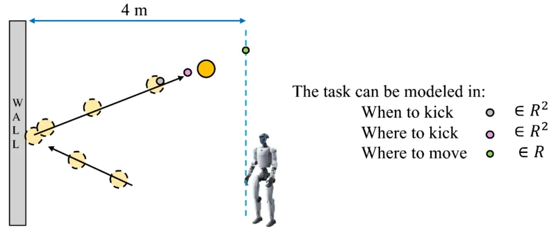
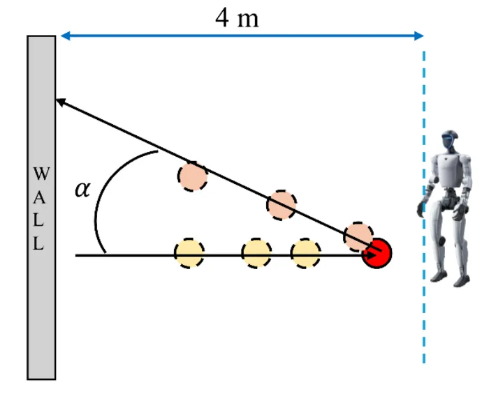
The environment consists of a 10 m wall, the robot positioned about 4 m from the wall, and a ball. The objective is for the robot to kick the ball using only onboard perception, achieving a continuous wall-rally kick: the robot must decide when to kick, where to kick, and where to move, given its distance from the wall.
Previous Mentor Work
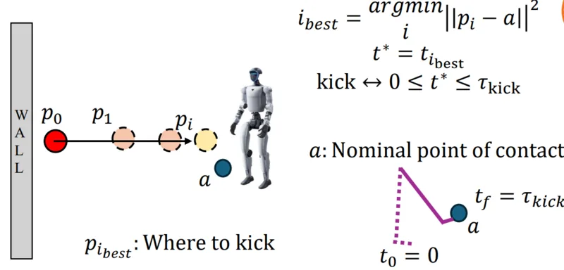
This task builds on a previous pipeline, TaskNPoint[11], in which, from collected data and kinematic retargeting, a policy is trained to imitate a kicking motion. Given that kicking motion, a trajectory estimator based on a Kalman filter with a single-integrator model predicts the ball's position, and an optimization algorithm selects when and where to kick. Because the baseline paper does not consider that the robot has to move in order to kick the ball, its experiments only have the robot wait for the ball.
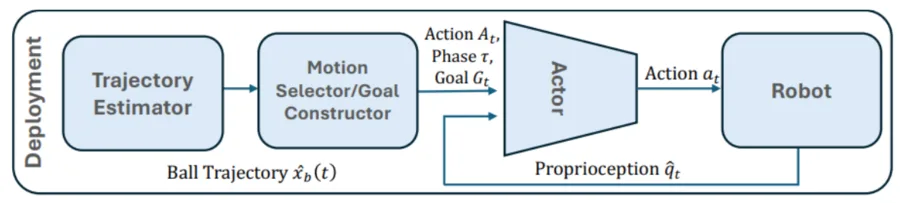
The optimization algorithm minimizes the distance between a point on the ball's estimated trajectory and the nominal contact point of the motion. Once the best point is selected, if its associated time falls within the motion's contact window, the kick is triggered. Since a motion has only one contact, the baseline randomizes that contact point during training to extend the range of reachable contact points.
Since kicking with a desired direction matters, we define a kick direction angle \(\alpha\), where \(\alpha=0\) means the robot does not need to move much, and stays stopped and waiting for the ball, reducing the risk of distribution shift, since during training the robot was only trained while stopped.
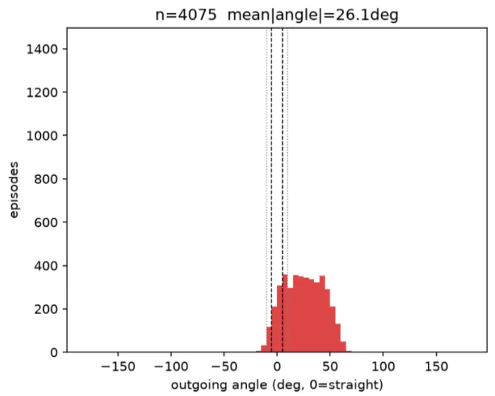
Across 4096 episodes with the robot stopped and the ball approaching from a random lateral position between -3 and 3 m, the outgoing kick angle distribution of the vanilla motion is skewed to the right.
When/Where to Kick Policy Design
To improve the kick's direction, we design a new policy that wraps around the kick policy, observing the ball's starting position and velocity, the robot's yaw, the lateral projection where the ball will cross the robot's line, and the time to that point. Its output is where to kick, and when to kick, given as a trigger distance.

The training rewards are: direction (the most important term, tied to the angle α), fall (to avoid kicking outside the kick policy's distribution), miss, straight (rewarding a conservative 5° angle), contact with the wall, and outgoing ball velocity.
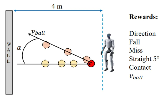
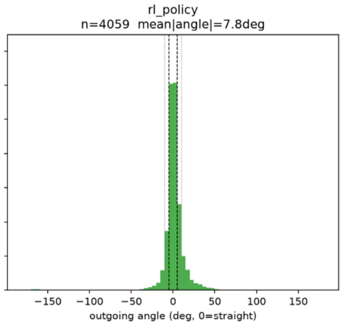
Over 4096 environments, the trained policy achieves a mean angle of 7.8°.
Control Loop Using Ground-Truth Information
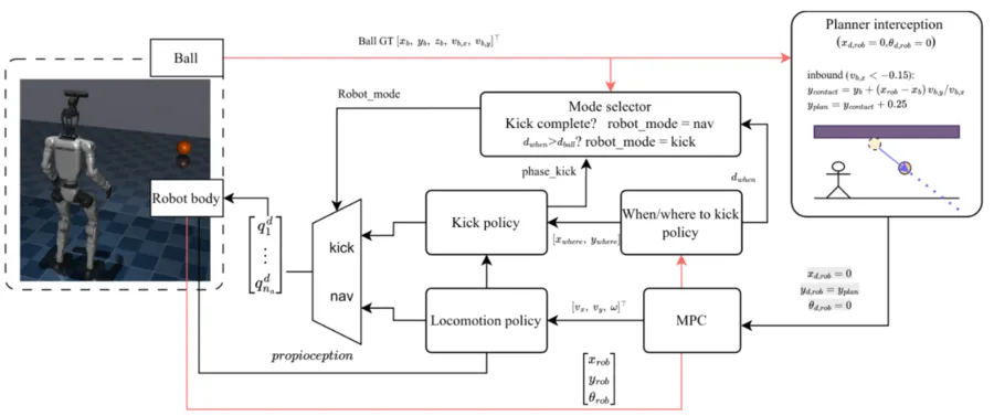
We first test the new policy using ground-truth ball position and velocity. A heuristic interception planner projects the ball's trajectory; the where-to-move point is the intersection between the robot's line and that projected trajectory. The robot is driven to that point by the MPC, always facing the wall, while the when/where-to-kick policy runs continuously and switches the robot from locomotion to kicking once the trigger distance is reached.
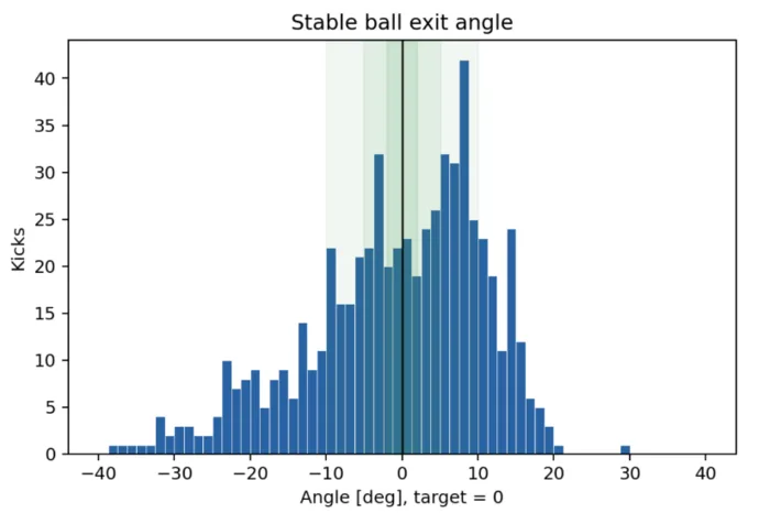
This achieves a continuous wall-rally kick, but the direction distribution is completely shifted relative to the standalone policy.
Control Loop Using No Ground-Truth Information
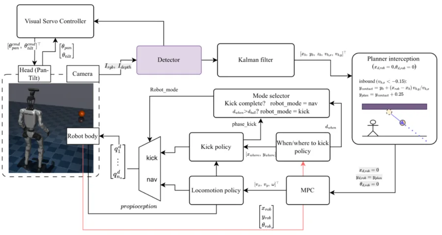
Relying only on onboard perception, we reuse the same visual servo controller and perception stack from Task 1, estimating the ball's position with a single-integrator Kalman filter. This still assumes perfect knowledge of the robot's own position, since the observer requires a non-inertial frame. With this loop, the robot achieves continuous rallies of up to 10 kicks across trials.
Conclusions and Future Work
A pan-tilt mechanism was designed and fabricated. A ball detector was also evaluated in simulation, yielding latency figures that can be used to improve domain randomization during training.
In Task 1, the pan-tilt mechanism allows the robot to decouple its tasks: while the body avoids obstacles and reduces its distance to the ball, the camera independently tracks the ball, removing the need to depend on external (offboard) sensing.
In Task 2, the when/where-to-kick policy improves the direction of the standalone kick policy, and the designed control loop achieves a continuous wall-rally kick. However, when tested using the pan-tilt-based controller with onboard perception only, the result drops to 8 kicks. The main reason is the noise generated while the robot moves, since this is the main source of feedback for the robot, and controller performance degrades accordingly.
Future Work
- Improve the kicking policy using Adversarial Motion Priors (AMP)[12], an approach well suited to both imitating a reference motion and achieving a continuous wall-rally kick.
- Design a policy that takes control of the pan-tilt controller, to explore behaviors that yield better feedback.
- Implement onboard odometry for Task 2: the Kalman filter still assumes ground-truth knowledge of the robot's own pose to compensate for its motion, which an onboard estimate would remove.
Final report coming soon.
References
- Dai, M., Compton, W. D., Li, J., Yang, L., & Ames, A. D. (2026). Walk the PLANC: Physics-Guided RL for Agile Humanoid Locomotion on Constrained Footholds. arXiv:2601.06286.
- Crismariu, C., & Cosner, R. K. (2026). MARCH: Model-Assisted Reinforcement Learning for the Perceptive Control of Humanoids over Sparse Footholds. arXiv:2606.10288.
- Werner, B., Yang, L., & Ames, A. D. (2025). Architecture Is All You Need: Diversity-Enabled Sweet Spots for Robust Humanoid Locomotion. arXiv:2510.14947.
- Yang, L., Bena, R. M., Wilkinson, M., Bahati, G., Navarro Brenes, A., Cosner, R. K., & Ames, A. D. (2026). Safe-SAGE: Social-Semantic Adaptive Guidance for Safe Engagement through Laplace-Modulated Poisson Safety Functions. arXiv:2603.05497.
- Bena, R. M., Bahati, G., Werner, B., Cosner, R. K., Yang, L., & Ames, A. D. (2025). Geometry-Aware Predictive Safety Filters on Humanoids: From Poisson Safety Functions to CBF Constrained MPC. IEEE-RAS International Conference on Humanoid Robots. arXiv:2508.11129.
- CubeMars. (2024). AK40-10 Robotic Actuator. cubemars.com.
- Jhoinrch. (2023). RH02 Plus USB to CAN FD Adapter. Product datasheet.
- Livox Technology. (2022). Livox Mid-360 User Manual. livoxtech.com.
- Wang, A., Liu, L., Chen, H., Lin, Z., Han, J., & Ding, G. (2025). YOLOE: Real-Time Seeing Anything. arXiv:2503.07465.
- Ultralytics. (2024). Ultralytics YOLO11. GitHub.
- Werner, B., Demler, I., Perona, P., & Ames, A. D. (2026). TaskNPoint: How to Teach Your Humanoid to Hit a Backhand in Minutes. arXiv:2606.26215.
- Peng, X. B., Ma, Z., Abbeel, P., Levine, S., & Kanazawa, A. (2021). AMP: Adversarial Motion Priors for Stylized Physics-Based Character Control. ACM Transactions on Graphics, 40(4), 1.